
The sensor coordinate frame or body frame is a local reference frame that moves with a sensor or platform, such as a drone, vehicle, robot, or missile. It defines orientation and movement relative to the sensor’s physical structure. Engineers use the body frame to express measurements like acceleration, angular rate, and velocity directly from the sensor’s perspective.
The sensor (body) coordinate frame—often called the body frame or vehicle frame—serves as a reference frame fixed to a moving platform, such as a drone, car, missile, or underwater vehicle. Engineers use this frame to describe the motion and orientation of the platform relative to itself, making it essential for navigation, control, and sensor fusion.
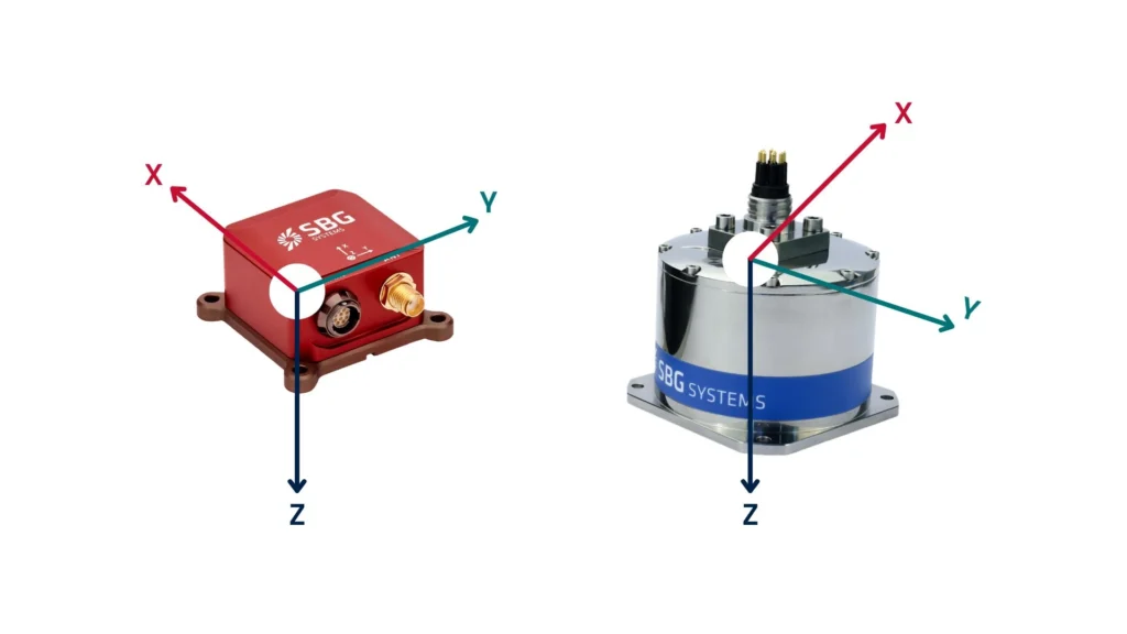
In most applications, users mount sensors such as IMUs, GNSS receivers, or AHRS units directly on the vehicle. These sensors report data in their own coordinate frame, which usually coincides with the body frame. It consists of three orthogonal axes forming a right-handed coordinate system:
- The X-axis points forward, in the direction of motion or the sensor’s nose.
- The Y-axis points to the right (starboard for marine or aircraft systems).
- The Z-axis points downward or downward relative to the sensor’s base, depending on the application.
This fixed orientation lets the system measure how it moves or rotates in its own space, rather than relative to the Earth.
Examples of Body Frame Applications
The IMU of a drone is responsible for measuring the acceleration and rotation in its own frame of reference. When the drone pitches forward, it senses angular velocity around its Y-axis. The system transmits this data to the flight controller, enabling the drone to stabilize and execute flight commands with precision. For instance, the drone’s autopilot system utilizes sensor data in the body frame to stabilize flight and execute maneuvers like yaw, pitch, and roll. The system interprets movements directly, expressing them as forward, lateral, and vertical motions relative to the drone’s own frame.
A self-driving car, on the other hand, detects its linear acceleration along the X (forward), Y (sideways), and Z (vertical) axes in its body frame. This capability enables the vehicle to adjust its speed, maintain lane control, and respond to changes in the terrain. This coordinate frame facilitates the interpretation of lidar, radar, and inertial data. The car’s control system uses these readings to make real-time driving decisions based on its own orientation.
A missile’s navigation system utilizes the body frame for orientation tracking. As it maneuvers, the onboard sensor detects rotational rates and acceleration in body-fixed axes, allowing precise course corrections. The onboard navigation system of the missile utilizes the body frame to track acceleration and angular velocity, enabling it to adjust its trajectory and orientation based on its current position and the coordinate frame’s orientation.
A robotic arm employs a body frame to calculate joint movements and end-effector positions. Each motor’s position and orientation are measured in this local frame to ensure real-time control.
Sensor Alignment Challenges
In practical applications, sensors are not always perfectly aligned with the body frame. To address this, engineers frequently implement frame rotation corrections, which align the sensor’s coordinate system with the vehicle’s body frame. This ensures precise readings for calculations related to position, velocity, and orientation. It is fundamental for any system that moves and senses its environment. It plays a vital role in real-time navigation, control, and stabilization, making it essential in aerospace, defense, automotive, and robotics systems.
Tell us about your project