In navigation, attitude refers to the orientation of a vehicle or object relative to a fixed frame of reference, which is typically defined by three rotational axes: pitch, roll, and yaw.
These axes describe the angular position and movement of the vehicle in three-dimensional space. Pitch refers to the up or down tilt of the vehicle’s nose, roll represents the side-to-side tilting of the vehicle along its longitudinal axis, and yaw denotes the left or right rotation around its vertical axis. Together, these parameters define how a vehicle is positioned and maneuvered in its environment.
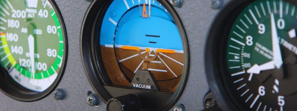
Attitude is crucial for maintaining stability, ensuring precise control, and enabling accurate navigation across various domains. In aviation, for example, attitude helps pilots or autopilot systems maintain level flight, execute turns, and adjust for turbulence.
Similarly, in maritime navigation, attitude control ensures a vessel stays upright and on course despite the challenges posed by waves and currents.
In spacecraft, attitude plays a critical role in pointing antennas, solar panels, or scientific instruments in the correct direction, especially when external visual cues are unavailable.
To measure and control attitude, systems like gyroscopes, accelerometers, and magnetometers are employed, often integrated into an Inertial Navigation System (INS). These systems work in conjunction with external data sources such as GNSS or star trackers to maintain accurate orientation.
Understanding and managing attitude is particularly important in dynamic environments, where external forces like wind, waves, or gravitational anomalies can impact a vehicle’s trajectory.
Effective attitude control, therefore, ensures safe and efficient travel, allowing vehicles to meet their navigational objectives with precision.
GNSS attitude solutions
GNSS attitude solutions provide the roll, pitch, and yaw angles, which describe the orientation of an object in space. These three components are essential for understanding the object’s attitude relative to the Earth’s surface or a reference frame.
- Roll refers to the rotation around the forward axis, affecting the left and right tilt of the object.
- Pitch is the rotation around the side-to-side axis, determining the up and down tilt.
- Yaw is the rotation around the vertical axis, which defines the direction the object is facing.
These solutions combine data from GNSS receivers with additional sensors, such as accelerometers and gyroscopes, to deliver highly accurate and reliable attitude information.
This approach is particularly valuable in environments where precise orientation is crucial, like in navigation systems for aircraft, vessels, and autonomous vehicles. By integrating these diverse sensor inputs, the system ensures optimal performance even in challenging conditions.
Attitude Representations
Attitude represents the orientation or rotation of an object relative to a reference frame, such as the Earth’s surface. In navigation systems, this concept is critical for determining the object’s orientation in space, which could apply to aircraft, UAVs, ships, or other autonomous systems. There are several ways to represent attitude mathematically and visually.
1 – Euler Angles (Roll, Pitch, Yaw)
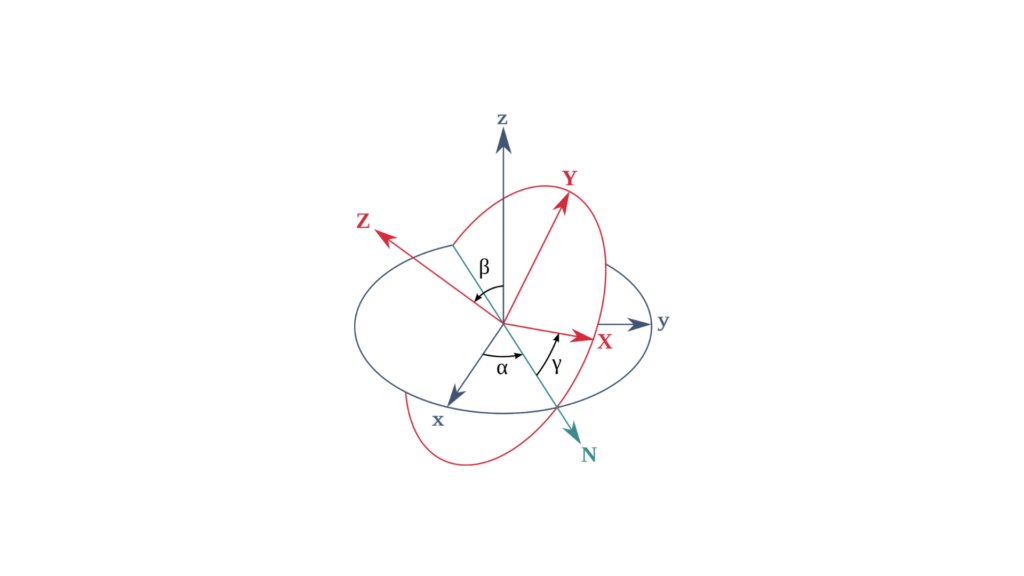
Euler angles represent an object’s orientation through three rotations: roll, pitch, and yaw. These angles describe rotations around three axes in a specific sequence, such as:
Roll (φ): Rotation around the front-back axis.
Pitch (θ): Rotation around the side-to-side axis.
Yaw (ψ): Rotation around the vertical axis.
Mathematical Representation
Euler angles can be represented as a 3×3 rotation matrix, where:
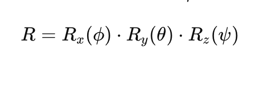
Here:
- Rx(ϕ)R_x(\phi)Rx(ϕ) is the rotation matrix for roll.
- Ry(θ)R_y(\theta)Ry(θ) is the rotation matrix for pitch.
- Rz(ψ)R_z(\psi)Rz(ψ) is the rotation matrix for yaw.
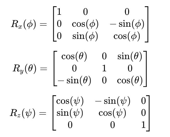
Each rotation matrix is given as:
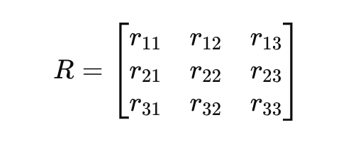
2 – Rotation Matrices
Rotation matrices offer an alternative way to represent attitude. In this method, a 3×3 matrix describes an object’s orientation in 3D space relative to a fixed coordinate system. These matrices are orthogonal, meaning the rows and columns are unit vectors. Consequently, the inverse of the matrix is simply its transpose.
Mathematical Representation
You can write a general rotation matrix 𝑅 as:
3 – Quaternions
Quaternions provide a more compact and numerically stable representation of rotation. They avoid singularities and gimbal lock problems associated with Euler angles. A quaternion 𝑞 is a 4-dimensional vector:
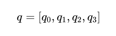
Where 𝑞0 is the scalar part, and [𝑞1, 𝑞2, 𝑞3] are the vector components. The quaternion representation of a rotation can be written as:
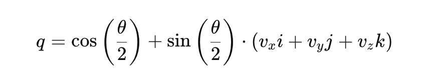
Here:
- θ is the rotation angle.
- [vx,vy,vz] is the unit vector representing the axis of rotation.
- i, j, k are the fundamental quaternion units.
Advantages of Quaternions:
- Avoids gimbal lock and singularities.
- More computationally efficient for interpolation.
4 – Direction Cosine Matrices (DCM)
A direction cosine matrix is similar to a rotation matrix and also describes the orientation of an object. The DCM relates the coordinates of a vector in one frame to the coordinates of the same vector in another frame.
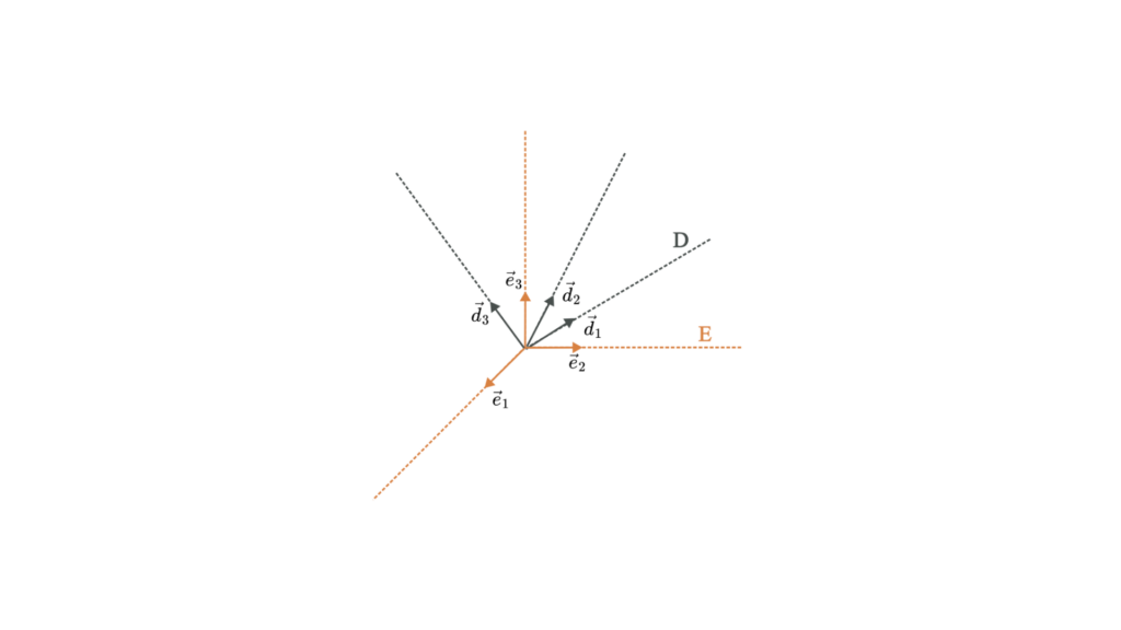
Mathematical Representation
A direction cosine matrix 𝐶 is a 3×3 matrix that defines the relationship between two coordinate frames:
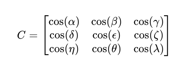
Where the elements cos (⋅) represent the cosine of the angle between the vectors of the two coordinate frames.
Tell us about your project